Feature:
This module is widely applicable to the design and development of home electronics and electronics products for the electronics enthusiasts.
It can be used as a signal input source of the SCM, and is especially suitable for the design of electronic circuits for students in universities and colleges.
Can be docked with a single chip, or an amplifying drive relay or a small DC motor.
Module board with self-locking, interlocking, triggering (inching), high level, low level, machine equipment, automation equipment modification, PLC industrial control, Arduino robot, intelligent product
Product introduction:
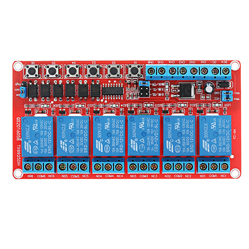
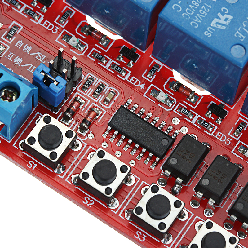
Each road has a signal light to clearly know which switch is working.
There are three options for self-locking/interlocking/trigger (jog).
The self-locking is pressed once, the relay pulls in, press again to closed. The self-locking type 6 channels are independent of each other, and can also be connected to an external trigger switch (CH connection terminal), triggered by a high or low level (optional), and can control 6 channels at the same time, such as lighting control.
When the trigger (jog) is pressed, the relay pulls in and releases to closed. It is also possible to connect an external trigger switch (CH terminal connection) with a high or low level trigger (optional). Applicable to such as electric gates, electric door locks, and MCU docking only need a high or low pulse circuit and other circuits.
The interlock is a typical application of the fan design. When press S1, the relay pulls in; when press S2, S1 disconnect, the relay of S2 pulls in.
The 2 channel interlock can only be connected one way, and it can also be connected to an external trigger switch (CH connection terminal), triggered by a high or low level (optional). Practical applications such as electric fan gear switch circuit.
Features:
1. Double-sided design PCB, 6 channel independent design, mutual interference;
2. The use of single-chip design, stable and reliable performance, strong anti-interference, will not trigger falsely, superior performance;
3. Humanized interface design, with a good terminal, can be directly connected to the lead;
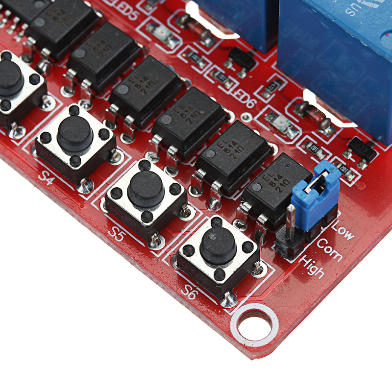
4. The trigger end has optocoupler isolation, the trigger power supply can be independent external power supply, truly completely isolated;
5. With 6 tactile switches as product testing, direct test product stability;
6. With power indication (green LED) and 6 switch indications (red LED);
7. The relay control the load, and the load can withstand under 250V 10A (AC) and 30V 10A (DC);
8. Module size: 110x57x18.5mm, weight: 100g;
9. Design has 4 bolt holes: spacing 104×51, aperture 3mm.
Electrical parameters:
Trigger voltage: It is 12V voltage trigger, needs to connect a 5.1-6.8K resistor in series to trigger, otherwise it will burn the chip.
Supply voltage: 12V DC
Quiescent current: 23mA
Operating current:
1 channel 69mA
2 channel 116mA
3 channel 162mA
4 channel 207mA
5 channel 252mA
6 channel 297mA
Load: 250V 10A (AC) or 30V 10A (DC)
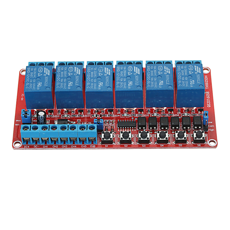
Module interface:
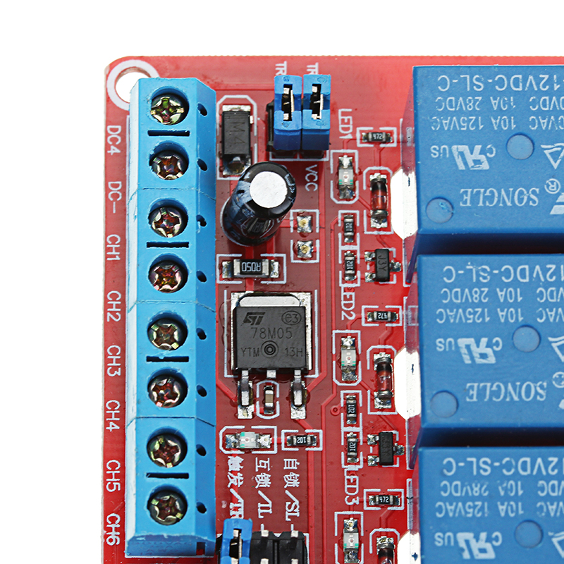
Power input:
1. DC+: positive power supply for the module, the same voltage as the relay;
2. DC-: module power negative;
Trigger side:
1. CH1-CH6: Corresponding to 1-6 relay trigger control terminal, support high or low level trigger trigger;
2. TRV+: external positive trigger power supply, if you want to connect external trigger power, the jumper between RTV+ and VCC should be unplugged
3. TRV-: external negative trigger power supply, if you want to connect external trigger power, the jumper between RTV- and GND should be unplugged
4. 6 micro switches: Corresponds to 1-6 relay test keys, valid at low-level trigger;
5. High/low level trigger selection. When COM and L are connected, low level trigger is valid. When COM and H are connected, high level trigger effective
Relay output:
1. NO1-NO6: Relay normally open interface, before pull-in the relay is vacant, after pull-in, short circuit with COM.
2. COM1—COM6: Relay common interface
3. NC1—NC6: Normally closed relay interface, before pull-in the relay short circuit with COM, after pull-in the relay is vacant.
Package includes:
1 x 12V 6 Channel Relay Module