ATmega328 DC 7-12V 8MHz DIY LCD Digital Transistor Tester Kits With Shell MOS NPN PNP LCR JFET P-IGP
$24.73
Features:
The processor uses high performance MCU ATmega328, and uses external 8MHz crystal oscillator as the system clock.
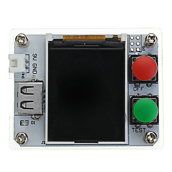
Using 1.8 Inch LCD display, resolution of 128X160, support 65536 colors.
Single button operation, support automatic shutdown for reducing power consumption.
Support battery power supply, shutdown current less than 20nA.
Each measurement time is about 2S, and only when measuring capacitance or inductance, the measurement time becomes longer.
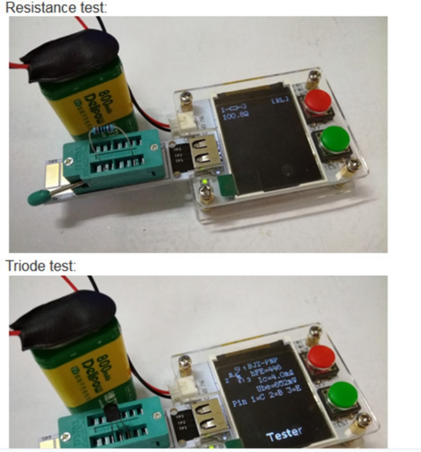
Automatic detection of NPN, PNP bipolar transistor, N channel, P channel MOSFET and JFET, diode, double diode, P-IGPT, thyristor, double thyristor and so on. For some thyristors and double thyristors, the transistor tester can not be tested when the current and current can not be satisfied. For some IGPT with a driving voltage of more than 5V, the transistor tester can not test it.
Support the identification of the pins of test elements.
Supports the measurement of current amplification factor and base emitter turn-on voltage of bipolar transistors.
The Darlington transistor can be distinguished by the turn-on voltage and the current amplification factor.
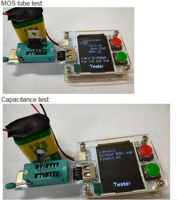
The gate threshold voltage, gate capacitance and drain to drain source resistance of the RDSon under the 5V gate voltage are tested to test the MOSFET.
Supports simultaneous measurement of two resistors, and data is displayed in four bit decimal format. Support potentiometer test, but when the potentiometer is adjusted to one end, at this time can not distinguish between the intermediate pin and the end pin.
The minimum resistance resolution is 0.01 ohms, and the maximum resistance is 50M ohm.
A capacitor can be measured with a capacitance range of 25pf~100mF and a resolution of 1pF.
The capacitance less than 25pF can be measured by parallel with another known capacitance greater than or equal to 25pF, and the measured capacitance value can be obtained by subtracting the known capacitance value.
When the capacitance greater than 90nF is tested, the series equivalent resistance is also displayed, with a resolution of 0.01 ohms.
When the capacitance greater than 5000pF is tested, the voltage loss after the test pulse can be measured, and the quality factor of the capacitor can be estimated by this parameter.
Supports simultaneous measurement of two diodes with additional display diode voltage drop.
LEDs are identified as diodes, and the test voltage drop is much larger than that of conventional diodes. The two-color diode is identified as two diodes.
The equivalent inductance of the resistor less than 2100 ohms is also measured at the same time, with a range of 0.01mH~20H, but the measurement accuracy is not very good.
Program with self-test function, support a variety of parameters calibration.
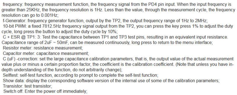
Support frequency generator function, output by TP2, output frequency range from 1Hz to 2MHz.
Support a fixed frequency signal output from the TP2, you can adjust the duty cycle by the button.
Special attention:
The capacitor must be discharged before testing the capacitor, otherwise it may damage the test pin.
When testing the components on the circuit board, it is necessary to disconnect the power supply on the circuit board, and the residual voltage is not allowed on the test equipment.
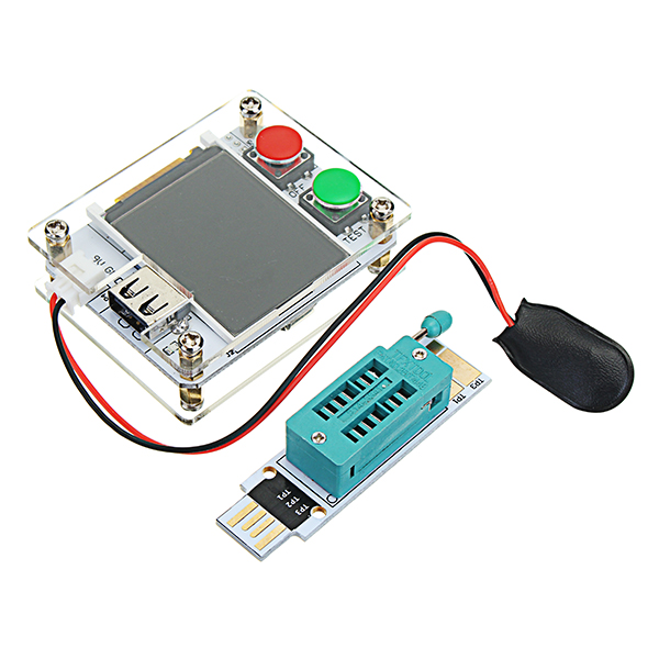
Hardware circuit:
Each interface is illustrated as follows:
J1: 2.54-2PIN white seat is used to input DC 7~12V voltage;
S1: red button, reset button;
S2: green button, operation button, used for one button operation of the entire circuit board;
Instructions:
1. Components placed
The transistor tester is very simple, and the test pins TP1, TP2 and TP3 are all in sequence. For only two pins, the components only need to be placed to any two test pins. For three pins of the components, randomly placed three test pins. Two resistors and two diodes can be tested at the same time.
2. Press the S1 reset button to shut down, and then press the S2 boot key to start a new measurement.
3. After the start of the long press S2 (more than 1S), enter the additional function selection interface, after a short press for moving the cursor on the attachment, long into the function interface button corresponding to the cursor interface, the various functions are as follows:
Package included:
1 x ATmega328 digital transistor tester kits with shell