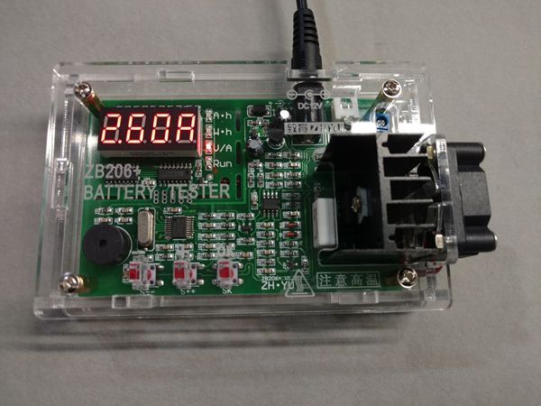
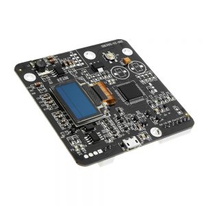
ZHIYU ZB206 12V Multi-Function Battery Capacity Internal Resistance Tester 18650 Battery Tester
$24.38
Feature:
Supply voltage: DC 12V
Working current: <0.2 A
Power port: 5.5 x 2.1mm Power Port
Maximum battery input voltage: 8.5V
Maximum error of discharge current: 1%+2mA
Voltage measurement error: 1%-3D
The maximum error of the overall measurement results: 0.1-0.2A 2.5%, 0.3-0.5A 1.6%, 0.6-1.0A 1.2%, 1.1A-2.6A 1%
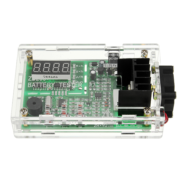
Circuit board size: 118 x 74 x 43mm
Specifications:
Quick Learning Instructions (Factory Default State):
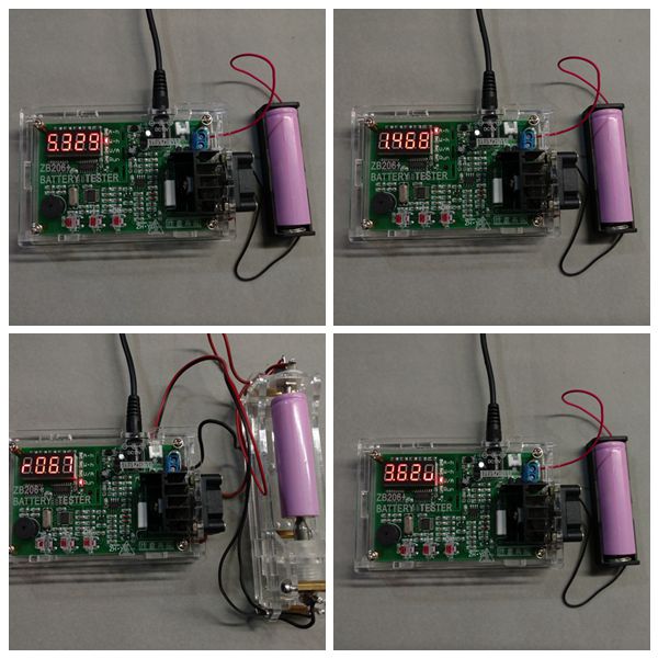
1. Connect the positive pole and negative pole of a fully charged test battery to a blue connector BAT+ and BAT- with a short and thick connecting wire as far as possible! Power up the tester with DC 12V (power up 5V USB using micro USB power supply) and the tester is switched on showing preset current.
2. Press “S–” or “S++” button to change the preset current from 0.1 – 2.6A; after the current change, press “SK” button to start test (if Err* shows, please refer to the instructions as follows); the tester automatically choose end voltage; “RUN” light lights up; LED display data, capacity Ah, energy Wh, voltage V, and current A take turns to show. After the test is finished, “RUN” light goes out and LED display showing Ah blinks rapidly with beeping at the same time.
3. Press “SK” button to make the tester stop blinking and beeping after you stop the test; check the capacity Ah, energy Wh, test process average process voltage V of the battery by pressing “S–” or “S++” button; press “SK” button again and the tester returns to the starting-up state and the previous operation can be done again to test the next battery.
Warning: You must press the button again after the test to clear backup data; if not, the backup data will be saved all the time and even in power-off state of the tester!
Error code Err* meanings and treating methods:
Err1: Overhigh battery voltage; please make sure that battery voltage is lower than 8.5V before test.
Err2: Battery voltage is too low (lower than setting end voltage); please confirm the battery voltage and set it again; battery reversal also shows Err2.
Err3: Battery cannot withstand current or wire is too thin or thick; please set down the current to do the test using thick and short wire with good electrode contact.
Err4: Damaged mosfet and normally speaking, bad transformation can lead to this problem; you can change the mosfet with model number P75NF75, ect..
Err5: Power overflow when power limit function is used (LPon); that means power in setting current is over limit.
Err6: Tester power supply voltage is out of range; please use the power supply with correct voltage!!
Note: Press any button to return to the initial state when it shows Err1 to Err5.
Full Function Detailed Instructions:
1. Test Operation:
1.1 Make sure that the tested battery is full charged.
1.2 Connect the positive pole and negative pole of a fully charged test battery to a blue connector BAT+ and BAT- safely and reliably with a short and thick connecting wire as far as possible! If it is 4-wire test mode, please connect the positive pole and negative pole of the holder’s voltage test wire to BV connector “+” and “-”. Power up the tester with DC 12V (power up 5V USB using micro USB power supply); it is current setting state after the tester is normally started up; LED display shows setting current (e.g. 1.00A); press “S++” or “S–” button to adjust setting current (long-press the button to quickly make the number go up and go down); when it is okay, press “SK” button.
1.3 Automatic Identification Mode (Factory Default Mode): Tester automatically identify the tested battery type and choose the optimal end voltage and discharge mode; it comes to tested work procedure when it shows the end voltage for 2 seconds.
Manual End Voltage Setting Mode: Manually set end voltage in the mode; press “S++” or “S–” button to change battery end voltage (long-press the button to make the number go up and go down); P*.*u stands for continuous current test mode and b*.*u is the classical non-continuous current (open load voltage test) test mode (mainly used for counteracting wire resistance effect on 2-wire testing battery) and for example, P4.5u stands for continuous current test and end voltage is 4.5V. Setting range is b1.0u-b6.0u and P1.0u-P6.0u; please pay attention that when 4-wire test is started, non-continuous current test mode cannot be used! After setting end voltage, press “SK” button to do the test.
1.4 In test process preliminary stage, tester diagnoses the wire and battery; if there is something wrong with the wire or battery, the tester will not do the diagnosis showing fault diagnosis code Err* (please refer to the above part for error code Err* meanings and treating methods). After the diagnosis, the test is started; “RUN” light lights up; the discharge test starts; LED display data, 2 seconds A.h, 1 second W.h, 1 second battery voltage, and 1 second discharge current take turns to show with its indicator light being changed at the same time. After the test, “RUN” light goes out; LED display showing Ah blinks rapidly with beeping at the same time (set “bEon”).
1.5 Press “SK” button to make the tester stop blinking and beeping after you stop the test; check the capacity Ah, energy Wh, test process average voltage V of the battery by pressing “S–” or “S++” button; press “SK” button again and all of the display data will be cleared to return to the initial current setting state.
Note: The maximum count data of the tester is 80.00Ah or 500.00Wh and if one appears, the test will be finished! If you want to test the battery over the count data limit, please record the current result and start the second test with the second result being added.
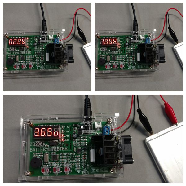
2. RES-V Test:
Please use standard 4-wire test holder or Kelvin test holder! Make sure that the tester and the holder are well connected according to the above “1.2” 4-wire test connecting wire’s requirements. Keep pressing “S–” button and power up the tester and the tester RES-V test function is enabled. Put the battery in the holder according to battery polarity and the tester shows battery internal resistance r*** (*** is internal resistance mΩ, e.g. r065 is 65mΩ and it does not show any value if it is overflow); at the same time press “SK” button and the V test is started showing battery voltage “*.**u”; press “SK” button to come to the internal resistance test…; for exiting RES-V test function, please shut off the tester.
RES test is DC pulse and its test result has deviation with AC test result; RES test can be used for quickly selecting battery.
Note: RES test cannot be used for testing dead battery.
3. Tester Working Parameter Setting:
Keep pressing “SK” button and power up the tester and tester working parameter setting is started; press “S++” or “S–” button to modify parameter; press “SK” button to come to the next and set the parameters in order as follows:
I Use 2-wire test for “LJ 2” (factory setting); 4-wire mode for “LJ 4”.
II “Auon” battery automatic recognition function is enabled (factory setting); “AuoF” battery automatic recognition function is not enabled and after it, set end voltage manually.
III “bEon” buzzer is enabled (factory setting); “bEoF” buzzer if not enabled.
IV “LPon” power limit is enabled (factory setting); “LPoF” power limit is not enabled. Warning: More than 12W discharge is allowed for “LPoF” on condition that strengthening heat dissipation is the first thing and if not, mosfet may be burnt!
V “SF00” “SF01”…… “SF10”, fan control enabled power numerical value: the current discharge power is over the latter two digits (W), fan control switch is on; “SF00” means that once the discharge is started, fan control is on.
After the fifth setting is finished, press “SK” button and all of the setting parameters are saved and the tester is restarted to start work again.
4. Parameter and Result Being Automatically Saved and Backed up:
4.1 When setting current and end voltage (automatic mode not enabled) and starting a test, current and end voltage parameter will be automatically saved; the parameter will be the default value next time.
4.2 When the tester is in discharge process and if it is suddenly powered off, tester will automatically save the current setting numerical value, working state, and test result; power up the tester with DC12V again and the tester will automatically restore discharge process.
4.3 When the tester blinks rapidly with beeping after the test being finished, the test result is backed up to avoid data loss before reading it; if you do not press button, the tester will not exit this state even if it is powered up again! If data is read after you press any button, backup will be cleared; after it, press “SK” button again or power it up again, it will come into initial current setting state.
“4.2” and “4.3” can make sure that a test is not affected by midway power cut! When portable power source is tested, the tester being powered up again comes into test finished state because portable power source with no load is being automatically turned off; if you need to continue to test, please record the current result by yourself and start a test again; please add the first test result and the second test result to get the final test result by yourself.
5. Test Process Midway Quit or Midway Current Modified:
During discharge test process, press “S–” button to quit test and clear the result; if you need to midway modify discharge current or end voltage, press “S++” button to quit test without clearing the result and after the setting, press “SK” button to continue the test.
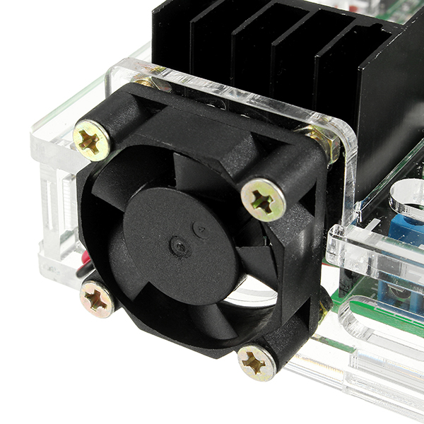
6. How to Use the Fan:
Tester has fan control design; connect the fan’s negative pole to LED display bottom right corner solder labeled with “F” and connect the fan’s positive pole to power supply’s positive pole to enable fan control function; please refer to “2” for control parameter setting.
Note:
a. “F-” maximum current is 0.2A and must not choose the fan over 0.2A!
b. If fan is installed for 5V version, only 5V fan is used because 12V output current of boost DC-DC is limited and it cannot load fan at the same time and the fan’s positive pole should be soldered on power supply connector boost DC-DC front near micro USB center’s rectangle pad (here input 5V).
Package included:
1 x ZB206 battery capacity tester (including shell and fan)